My car has always made a fair bit of noise from the front end. Recently it's also started to creak over bumps and there is a light rattle. I've also noticed a weeping of oil from one of the drive shaft seals (driver's side) and a tendency to get stuck in a knocking mode with UJ noise. All of this says to me that it's time for a front end overhaul. My car has now done some 140000 miles and things are definitely a little tired. I therefore decided to replace the shock absorbers, springs and strut top bearings, the lower wishbones and the drive shafts. I could of course change all of these items separately and independently but doing them all at once does give a certain economy of scale and should improve access. I'm not using original Ford parts because the car is too old to justify the cost BUT- this job took me twice as long as I had expected purely because I bought too low a quality of part. Its been an expensive lesson, but my advice now is always to go for branded parts. I used GRP shocks, FEBI top bearings and Sureline wishbones and driveshafts. I also had to replace one track rod end and so decided to do both and these were Starline or Unipart.
My plan for these jobs was to disconnect the lower ball joint and then remove the wishbone. Remove the driveshaft. Remove the brake caliper and disc and then remove the strut and steering knuckle as a unit. Rebuild the strut, refit strut and steering knuckle, fit the new wishbone and driveshaft, refit brake disc and caliper. In general this went well but I was unable to remove the steering knuckle completely because I couldn't remove the anti-lock brake sensor from the hub, or locate a convenient disconnection point at the other end. This meant I had to address the strut replacement in the wheel arch which wasn't ideal. The account that follows isn't exactly how things went- the first time I did this on the driver's side it took 4 days and some new parts to replace breakages. The passenger side was then done in 6 hrs and much more successfully! I have removed the dead ends and put in all the lessons learned, so hopefully this should show you what actually worked.
Before jacking up the car, remove the trim plate/hubcap
Then loosen the hub nut with a breaker bar. Its really tight (290 Nm) so you may need to put it in gear and have someone press the brake pedal as well!. Don't remove it just break the torque.
Also loosen the strut top nut from inside the engine compartment. Again-DO NOT REMOVE, just loosen. I used a go-through socket set with a hex key to hold the strut. Also at this point draw round the three strut retaining nuts with a sharpie o/e as you will need to refit these in the same position to maintain camber.
 |
| Loosening strut top nut. Note the outlines of the three fastening bolts drawn in felt pen. |
You can then jack up the car and remove the road wheel. I supported the car on axle stands at the sill jacking points. I used axle stand pads with a pinch weld slot to avoid damage.
 |
| Note route of brake pipe and antilock system sensor wire |
You can then see the brake hose- note the way that its curled through its supporting clip, and the wire serving the anti-lock brake sensor. You should also locate the shock-absorber to steering knuckle pinch bolt. Its inserted from the front.
 |
| Shock absorber to steering knuckle (hub) pinch bolt seen below brake hose attachment point. |
Its a good idea to loosen this now whilst the strut is still well supported- again you will need a breaker bar.
 |
| Loosening the strut to hub pinch bolt |
Moving down to the bottom of the steering knuckle, locate the lower ball joint pinch bolt. This is a Torx-headed bolt inserted from the rear and held by a nut at the front.
 |
| Lower ball joint pinch bolt behind disc |
I found that the nut unscrewed fairly easily and in theory the bolt should then tap out to the rear. However this is an area with a lot of weather exposure and it tends to corrode in place. Use plenty of spray penetrating oil on the bolt and in the pinch groove (remember this will need to be cleaned off the disc later!). It helps if you can use an impact wrench on the torx head as you hammer the drift. Mine was very tight although it did eventually come out with a drift. Corrosion on the bolt was obvious and the process destroyed the Tox head so new bolts will be needed.
 |
| Ball joint pinch bolt- in poor condition. |
You can then use a long drift slipped behind the knuckle to bear on the rivets of the lower arm. Hammer this down to break the ball joint taper- again this will be tight. I found that none of my ball joint separators would fit- although the fork type probably would.
 |
| Long drift slipped in behind the disc and bearing on the rivet heads of the wishbone to ball joint. I did this in case the wishbone is to be reused although in my case I probably wont -it. |
The ball joint eventually came loose
 |
| Ball joint emerging- note rusty penetrating fluid. |
and you can bend the wishbone down to disengage the ball joint completely from the steering knuckle.
 |
| Bend the wishbone down and slip the ball joint out completely |
I could now remove the lower arm (wishbone). The wishbone is held by a pivot bolt at the front and a metal bracket (3 bolts) at the rear. Here the front bolt is loosened with the breaker bar. Its a 15mm bolt with an 18mm nut on the rear. These bolts are also tight and will need a breaker bar to start them.
Then you need to hold the nut in a spanner and buzz the bolt out from the front. Take the nut off but don't remove the bolt just yet.
 |
| Front wishbone mounting nut- the 15mm bolt head is visible. Once loosened hold the rear nut with an 18mm spanner and buzz the front nut off. |
The rear mounting is a bracket that slips into a slot in the subframe and is then retained by three bolts; the group of three seen centrally here. The largest of these is actually a subframe retaining bolt and the two smaller bolts fix the bracket into the subframe.
 |
| 3 bolts holding the rear wishbone mounting. The largest doubles as a subframe mounting but the two smaller bolts outboard of this one hold the bracket to the subframe. |
 |
| Removing the largest of the rear mounting bolts- the sub-frame mounting bolt. |
Remove the sub-frame retaining bolt, and then the two bracket bolts. Finally remove the front pivot bolt completely and pull the wishbone out from the sub-frame.
All bolts removed. Subframe bolt has the wide washers and a pointed end.
The wishbone should come out relatively easily although its awkward to avoid jamming it on the strut/hub but this should be loose enough at the top to move out of the way.
 |
Wishbone removed.
|
Unclip the brake hose from its attachment on the strut using a screwdriver to tap the clip backwards...
 |
| Tapping the brake pipe securing bracket fixed underneath the shock absorber bracket. Tap it inwards to wards the motor |
... and out of the bracket. The brake pipe can then be disengaged.
 |
| The clip should slide out. Good idea to wire brush it and put some corrosion block grease on when refitting. |
Remove the brake hose from its fastening on the strut but note the way it is routed as its easy to get this wrong when refitting.
Unclip the antilock brake sensor wire from its mounts on the strut bracket and the inner wheel arch.
 |
| Anti lock brake cable removed from its support bracket. This bracket is attached at the drop-link top mount. |
I next set about removing the brake caliper by unscrewing the two bolts at the rear. The caliper is left suspended by a bungy in the wheel arch to avoid damaging or straining the flexible brake pipe
 |
| Top brake caliper securing bolt being removed. |
Once the caliper is off then the brake disc just lifts off- remember to clean any oil off this!
 |
| Brake disc lifts off. |
You can now unscrew the hub nut- luckily it should be loose and will just buzz off with an impact wrench
 |
| Impact wrench to buzz off the hub nut |
In order to withdraw the driveshaft the hub needs to come forwards. Although the nut is gone, the strut is still quite rigid and so its a good idea to loosen the three strut-top nuts at this point so that it has some freedom to move.
 |
| Loosening the three strut-top nuts, note that their positions are marked in pen. |
The drive shaft can then be pushed back through the hub.
 |
| Nut off, the shaft is now free to move backwards. |
You can use a hub puller or refit the nut and hammer it whilst pulling the hub forwards.
 |
Drive shaft slipped back through the hub, some corrosion on the splines meant this was a little tight but no real problem and it went easily with a little hammering.
 |
| I also used a 2 hole puller on the driver's side- again this worked very well but I had to use a small socket as a spacer since the push bolt wasn't long enough to push the driveshaft right through. |
|
..and the splines should slip through releasing the hub end of the shaft
 |
| Drive shaft disengaged. |
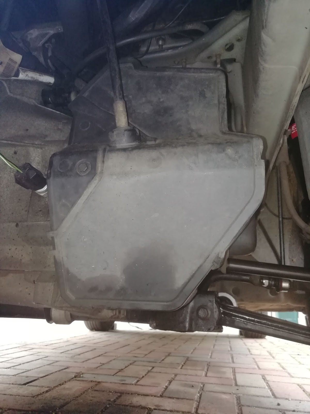
If this is the first drive shaft to come off then there will be considerable oil in the gearbox and it will be released when the strut comes out. I was under the impression that my car had no gearbox drain plug... Not so! I found it later and draining the oil in a controlled way would have been preferable! Anyway place a drip-pan under the gearbox shaft entry.
 |
| Driveshaft entry to gearbox |
You can then use a short lever to catch the end case of the drive shaft and tap it smartly backwards. It can be fiddly but the internal snap ring will release and the drive shaft will pop out. Releasing quite a considerable amount of oil if not already drained.
 |
| levering the driveshaft out of the gearbox |
 |
| Drive shaft removed (LHS), note drain pan. |
If you are removing the rhs driveshaft then the process is very similar but there dorsn't seem to be a snap ring on this side and the shaft came out more easily. You will need to release the intermediate drive-shaft bearing clamp though and this is held on by 2 x13mm flange nuts and the rear one is quite awkward to get at. I managed using a 3/8 drive deep socket.
 |
| Intermediate bearing support bracket- this is actually photographed with the new drive shaft as I forgot during disassembly! |
The shock absorber is now held to the steering knuckle (hub) via the pinch bolt joint loosened earlier. Its attached to the anti-roll bar via the drop links. In addition the hub is attached to the track rod by the track rod end ball joint. These attachments will all need to be undone, so start by removing the strut-to-hub pinch bolt loosened earlier.
 |
| Removing strut to hub pinch bolt |
Then using a go-through socket or a wrench hold the drop-link stud with a hex key and unfasten the nut. The top fastening also secures the antilock brake wire clip bracket.
 |
| Removing drop link top bolt- hold the ball joint shaft with a hex key whilst unscrewing the nut. |
The rear connection is a little more awkward but is removed in the same way- I needed a shorter hex key. I'm fitting new drop links too so these could be discarded.
 |
Removing the lower drop-link fastening. I'm aware that this pic shows some continuity errors because I actually took it during reassembly but I wanted to show here how the nut was accessed.
|
 |
Drop link removed and antilock brake clip bracket.
|
The track rod ball joint was unscrewed the same way using a go-through socket and a hex key.
 |
| Unscrewing the track rod end. |
and the joint broken using a separator .
 |
| Track rod end released. |
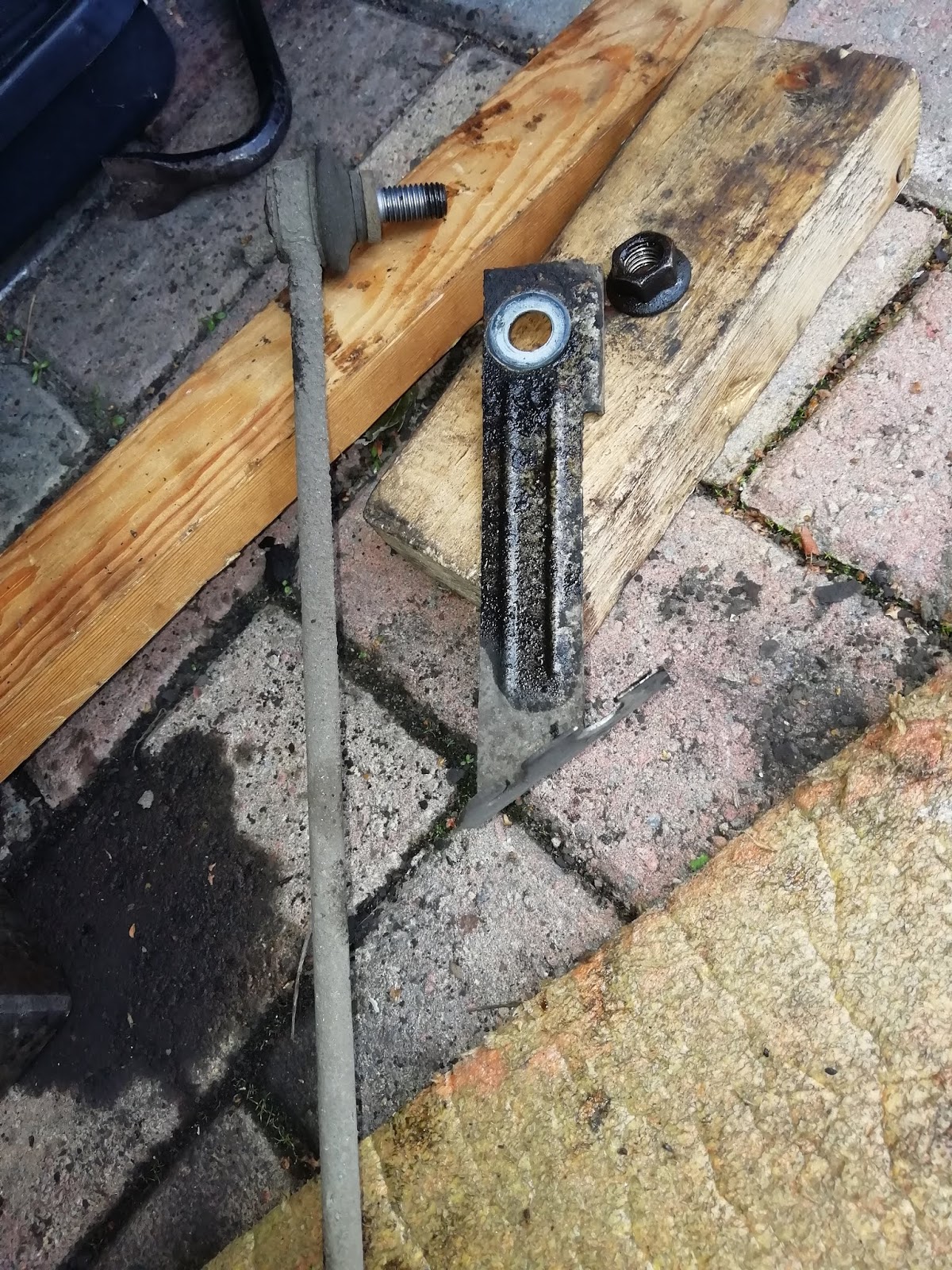
A note here that when I tried to release the driver's side, the hex key had corroded out and I couldn't stop the shaft from turning. Eventually I had to saw it off and replace the track rod end- probably just as well to replace it at this stage as it looks to be original. I decided that perhaps replacing both is a good idea. Unfortunately it means I will need to get the car retracked immediately.
At this stage it would be great if I could have removed the hub/strut assembly completely as I had planned. Unfortunately I found I couldn't remove the anti-lock brake sensor wire and neither could I find a convenient point to detach it. As the sensor is delicate I was forced to leave the hub in the wheel arch and this meant removing the strut there as well. This is hardly convenient as it is preferable to take everything to the bench but its possible.
The hub is now held only by the tightness of its fit on the shock absorber base. I used a hammer to slide along the line of the shock and tap the hub downwards. Support the strut as much as you can to avoid damaging the top mountings. I can't see any other way to detach the hub and I would really very much rather that the sensor had been removed.
 |
| Sliding the hammer head down the shock onto the hub. |
This loosened the hub which began to slip off the shock. I used a steel hammer to start it and then a deadblow. If you hammer the knuckle use a soft hammer or a wood block to avoid cracking the casting.
 |
- Hub slipping down the shock absorber. Time to swap to desdblow mallet
|
The hub was finally detached completely. I hung the hub in the wheel arch using a bungey to join the brake caliper- well it is nearly Christmas!
 |
| Hub freed from strut and suspended in wheel arch. Note brake caliper likewise behind. |
The strut could now be removed by unscrewing the three top nuts completely. Support it from beneath as it comes free and remove it from the car.
 |
| Strut removed. |
This marks a turning point as now everything is off the car there is little more dismantling required before reassembly can begin. I opted to fit new driveshaft oil seals at this point. The oil seal is the black ring lining the shaft entry, I inserted a tyre lever to fit just behind the seal and gave it a sharp tap downwards. This levered the old seal out.
 |
| Levering out the old seal- you need to slip the lever up behind the black ring of the seal and in front of the metal ring visible in the opening. Try not to scratch the edges of the hole with the lever |
The new seals are surprisingly cheap- mine were Cortico.
 |
| New seal |
Clean out the opening with a clean rag to remove any grit and lightly oil the new seal. The seal just fits into the opening and taps in, I used the old seal as a drift to avoid damaging the new.
 |
| New seal in gearbox driveshaft entry. |
It was my intention to rebuild the struts using new shocks, springs and top mounts but reusing the dust covers and bump stops. To recycle these I needed to dismantle the strut and remove them. To dismantle the strut and rebuild it you need to fit spring compressors, mine were made by Sealey. Once the springs are contained the strut top nut could be removed completely, again using the go-through wrench and hex key.
 |
| Springs contained in compressors, unscrewing the strut top nut. |
The strut top bearing assembly fitted to the rubber gaiter and internal bumpstop then lift off
 |
| Strut top bearing and gaiter |
The top bearing assembly unclips from the internal bumpstop, I'm changing these components.
 |
| Bearing separated from the gaiter. |
Starting reassembly did raise a few questions. The old shocks had a nylon sleeve that acted to grip the base of the gaiters, the new shocks had instead a steel disc welded on in this place. However the disc is too narrow to adequately grip the gaiters which just flop about at their base. Its not possible to transfer the nylon sleeve (although it does tap off) unless you reduce the diameter of this welded disc- I didn't want to take a grinder to my brand new shocks!
 |
| Old shocks (left) with nylon sleeve that grips the base of the gaiters. New shocks right have a welded on disc but this is smaller diameter than the nylon sleeve and doesn't grip the gaiters.. |
However the left-hand shock had clearly suffered some damage- it had experienced one hell of a compression and the internal bump stop was broken and the nylon sleeve cracked on that side.
 |
| Nylon sleeves removed from old shocks- note damage to the lhs sleeve. |
There were also indications that the shock was starting to leak so replacement is clearly due. I also wondered if the poor fit of the gaiters to the new shocks was actually caused because they had stretched? Perhaps new ones would better fit these shocks? The gaiters and bump stops are available as a Monroe kit PK168. I obtained one of these, but sadly it didn't help the fit, but at least I have intact bumpstopsS to replace the damaged. Sadly it also means that as I'm not now using anything from the old struts I needn't have spent time dismantling them!
These shocks had been recommended by Autodoc and I did ask them and their UK subsidiary "Buycarparts.co.uk how this problem should be solved on several occasions. I found their customer services inadequate, they never answered any of my queries and in the end stopped answering my emails and let all my chat sessions time out. Very unimpressed.
Turns out KYB do make their own dedicatedvcovers and bumpstops but Autidoc didnt think to recimmend these when they suggested the shocks. I did eventually get a reply but this was nearly 2 weeks after the job was finished! I was also working on my Micra at the time ... and I still await a reply about the rear shocks they sold me for that!!
My new parts consisted of new shocks from KYB and springs from Anschler
 |
| Christmas! Lovely new bits! |
Top bearings are Febi Bilstein
The new top bearing comes as two parts which just clip together
 |
| top (left) and bottom (right) of the strut top bearing |
 |
| Bearing clipped together |
I reassembled the strut using the new spring, gaiters and top bearings incorporating the new bump stop. Before doing this remember to prime the shock by depressing it fully 3-5 times in a vertical position and allowing it to recover. Here I'm using a mallet to press as the strut hurts your hand! I'm not hammering it!
Clip the bump stop into the gaiter. Clip together the two sections of the top bearing- these are not handed although the shocks are, and then clip the gaiter/stop assembly into the top bearing.
 |
| Gaiter clipped into newly assembled strut top bearing. |
I then compressed the new spring and slipped it over the shock strut. The springs will only fit one way- larger diameter coil downwards, slip the spring into place and engage the end of the spring with the spring stop moulded into the spring seat on the shock. Then slip the gaiters down inside the spring, seating the top bearing on the top coil and feeding the strut through the bump stop and central hole. Finally add the top nut and screw it up a few turns simply to hold the top bearing on. The spring compressors can then be released.
 |
| Top cap held by nut, compressors removed. |
This does of course leave me with a loose bottom end to the gaiters and I'm not happy about that. Perhaps there is some way to split the nylon sleeve and glue the halves on top of the shock disc? At the moment I'm intending to tie the ends up with nylon pull ties, but I need to do that when the shocks are in the car and the springs are therefore compressed lowering the gaiters over the shocks.
 |
| New gaiter in place, but loose at the base- Its currently a bit too high to secure with a strap tie so I will need to attend to that later. |
I could then insert the strut back into the car. First I cleaned out the sockets in the hub into which the strut and ball joint fit. Both tend to accrue corrosion around the tops and this should be removed for a smooth fit. I used a small round edged file (lightly) followed by emery paper before washing everything thoroughly and applying some corrosion block grease.
 |
| Hub sockets cleaned and corrosion block applied. |
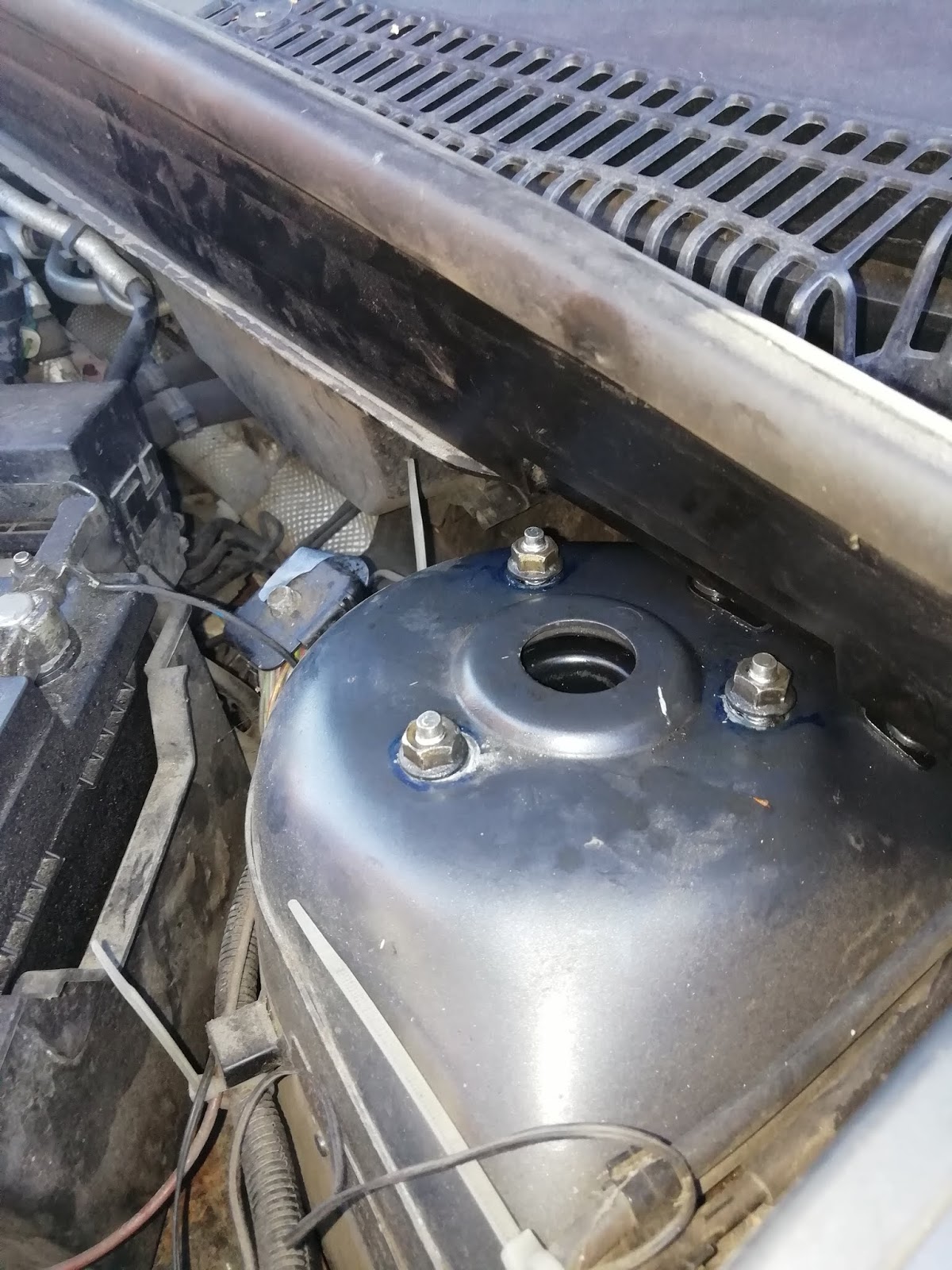
I then introduced the strut from inside the wheelarch
... securing it in place with the three top nuts- but only loosely at this stage.
 |
| Strut held by three top nuts |
The hub then needs to be tapped back onto the bottom of the shock absorber. It has a small hooked tag which must align with the slot in the hub ...
 |
| hooked tag on shock aligned above pinch slot in the hub. |
... and be tapped home
 |
| hooked tab entering pinch slot in hub |
The hub has to be tapped on until the pinch bolt hole aligns with the hooked tab
 |
| Hole nearly clear |
... so that the pinch bolt can pass though. Insert the bolt and tighten
 |
| Pinch bolt slipped home |
 |
Strut fitted loosely at the three top nuts with the steering knuckle tapped onto the base
|
I now wanted to fit the new driveshaft, but I've been caught out by driveshafts before- so this time I carefully compared the old with the new. There were no obvious differences, and crucially both were the same length.
 |
| Old and new driveshafts. |
I went ahead to fit the new driveshaft. Apply a little oil to the machined surface to help it slip into the oil seal without damaging it and then line it up with the driveshaft hole in the gearbox. Try not to get any dirt on the clean surfaces. Once its aligned, hold it as straight as possible and push it firmly and smartly into the box. If all goes well it should seat with a positive and very satisfying "clunk" You can then feel gently round it with your fingers to check that it has engaged with the oil seal. There should be no space behind the driveshaft and the oilseal. If its not quite gone home the problem may not be apparent until you try to refit the ball joint- or even later depending on how far out it is.
 |
| Keep the drive shaft straight and aligned and push it smartly back into the gearbox. |
You can then pull the hub outwards as the strut is still loose at the top and feed the splines of the new shaft into the hub.
K
 |
| Driveshaft slipped through. |
I next fitted the wishbone, The wishbone bracket and bush are tight fits in the subframe. Although the bracket can in theory bend to align, in practice its just too stiff to do this by hand and you really need to insert the tab of the bracket straight into the slot in the sub frame. In order to do this you will need to move the strut/knuckle assembly out of the way and in my case also raise the antiroll bar which blocks the direct approach. I positioned a jack under the point where the anti roll bar dips through the subframe
 |
| ARB dipping through subframe. |
 |
| Use a trolley jack just to raise the arb a few cm at this point and allow the wishbone to be inserted. |
This opens up the straight route in and the wishbone should push in without too much trouble. Push the bracket into place and fit the two small bolts by hand as soon as their holes align. Do not use a podger or you will damage their threads.
 |
| Bracket inserted and retained with the two small front bolts. |
Apply rubber grease to both sides of the front bush and push it back into the sub frame bracket, secure it with the through bolt done up to hand tightness.
 |
| Rubber grease on the front bush, bush fitted into sub frame mounting and bolt inserted |
Fit the rear sub-frame bolt and screw it in hand tight. You will probably need to persuade the wishbone into place with a little bit of mallet-work. Both the sub-frame mountings will be tightened up later when the car is standing on its own wheels.
Slip the hub back, bending the wishbone and ball joint as necessary to align the ball joint stump with the socket in the base of the hub. If this doesn't go easily then something is wrong and its possible that the shaft isn't fully home- or worse the driveshaft has become disarticulated. On my first attempt it became clear that something wasn't right, the ball joint couldn't be aligned with its socket in the hub but just jammed across it. Eventually I found that the driveshaft wasn't fully home and with a second attempt it slipped in and clicked. The ball joint then aligned easily.
 |
| Shaft not fully home in gearbox, Ball joint wont align |
 |
| Ball joint jammed across socket in hub |
 |
| Ball joint jammed. |
Realigning the driveshaft and pushing it in further did the trick! The ball joint slid home with a lovely satisfying click. You can then refit the bolt and tighten it up.
 |
New driveshaft re-positioned and inserted into the steering knuckle
|
Once fitted in place refit the pinch bolt- I used new bolts from Febi. At this point the strut is still flexible so it needs to be wriggled around until the three top nuts coincide with the markings made earlier. They should then be tightened to torque. Do thus before refitting the track rod end or drop links as you need the flexibility to move the strut.
All that remains now is to refit the drop links (including the bracket for the anti-lock system wire) and the track rod...
 |
| Refitting the anti-lock brake sensor wire in its clip |
... and clip the anti-lock sensor wire and brake hose back in place.
I torqued the strut top, hub to strut and ball joint to hub pinch bolts, track rod ball joints and brake caliper bolts whilst the car was raised, but the lower arm mounts and the drop links need to be torqued when the car is on its wheels. This presents a problem as if the car is standing on its wheels you can't get under it to reach the bolts! I refitted the wheels and then raised the car further on the jack. I could then slip some car ramps under the front wheels. You can then lower the car onto the ramps so that the wheels are weight-bearing and still just about get underneath! Its tricky as there isn't really enough room between the car and the ground to use a long torque wrench on the wishbone bolts. The rear wishbone is straight forward but the front is peculiar in that it should be tightened in two stages- firstly to 80Nm and then angle tightened through a further 55 degrees.
You can also tighten the hub nuts now but these are specified as 290Nm and none of my torque wrenches go that far. I borrowed a longer electronic wrench to do this.
Finally you need to refill the gearbox and sort out the gaiters before taking the car for wheel alignment.

Pinching the gaiter to tighten it around the weld disc on the shock and prior to addig the cable tie.


